In a previous article I built a simple line following robot. I had intended to follow this article up with more about building cooperating systems, but I’m afraid I got distracted! In particular I spent some time adding openCV (the open source image processing project) to leJOS. As a result I wanted a project to explore what was possible using openCV on the EV3, this article is the result!
One of the problems that I came across with my simple light sensor based line follower is that with this sensor the area viewed by the sensor is very small. Once the robot moves such that the line (or edge of the line) is no longer within the field of view then the robot is lost. There are a number of line following sensors available that make use of multiple light sensors arranged in an array to overcome this issue. I wanted to see if it was possible to create a similar “wide angle” sensor using a low cost webcam.
The first step (after getting openCV working!), was to modify the robot to add the webcam and remove the light sensor.
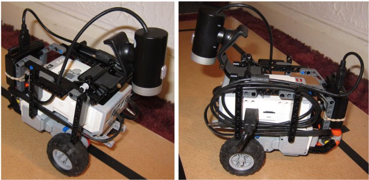
As you can see the results are a little messy mainly due to the usual cable management issues! I also had to add a small USB hub to allow me to use both the webcam and the WiFi dongle at the same time. So with the rover built time to create some code that would track the black line. In addition to the updated robot I have also updated the track I’m using:
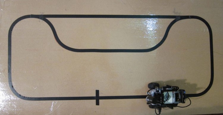
This updated track includes a “passing place” which I intend to use to allow one robot to overtake another, but that is for another post!
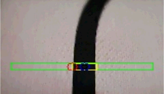
The image at the start of this article shows the webcam view seen by the robot. As you can see the black line shows up nicely, but how do we translate this image into a simple tracking signal that can be used by the robot? I wanted to reuse the code from my previous project so the signal I needed was a simple value that ranged from -1.0 to +1.0 with a value of 0 being generated when the line was in the centre of the image. The first step was define a smaller sample region. There are two reasons for this, the first is that trying to identify the “centre of the line” from an image like that shown that includes the start of a curve (or possibly several curves) is tricky where is the centre in this case? The second reason is that trying to process all of the image requires more cpu and by only using a smaller area it is possible to have a faster update rate. So in this case I selected a smaller rectangular region of the image to be the region of interest (to use an openCV term) or ROI. This ROI is shown on the above image as the outer green rectangle. Once we have this sub image we then need to identify the black rectangle within the image (shown as a yellow rectangle above) and then determine the centre of this rectangle and use this point as our target point. But wait what about these images:
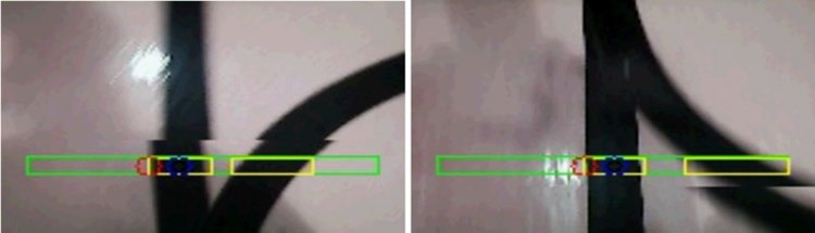
As you can see there are actually two black areas within the ROI (these extra lines are the start and end of the “passing place”). So we need to handle this. To do this I added an extra parameter to the tracking process. rather then track the centre of the line I track either the left or right edge, this point is then offset by half the width of the line to become the actual tracking point. In the above pictures you can see the detected edge shown in red and the final tracking point shown in blue. This step has an added advantage. By telling the tracker to follow a particular edge I can control how the robot follows the line, allowing me to easily select if it should go via the “passing place” or not). So now the detection process becomes:
- Capture an image
- Define the ROI
- Identify all of the black regions in this ROI
- Select the left most or right most edge of the corresponding region
- Offset this point to centre the tracking point
- Calculate the steering signal based on how far the tracking point is from the centre of the ROI
In practice there are a few extra steps required, it turns out that it is much simpler to do things like identify the regions if the image is turned into a simple black and white image, it also works better if the image is blurred a little (so any slight irregularities in the image are ignored). There are a number of good tutorials on openCV that help with this sort of stuff, I’ll leave you to explore them. So the core part of the line detection actually looks like this:
private float getMidPoint(int bias)
{
    vid.read(camImage);
    Mat roi = new Mat(camImage, new Rect(10, 2*camImage.rows()/3, camImage.cols()-20, camImage.rows()/12));
    Imgproc.cvtColor(roi, mono, Imgproc.COLOR_BGR2GRAY);
    Imgproc.GaussianBlur(mono, blur, new Size(9, 9), 2, 2);
    Imgproc.threshold(blur, thresh, 0, 255, Imgproc.THRESH_BINARY_INV|Imgproc.THRESH_OTSU);
    Imgproc.erode(thresh, erodeImg, erode);
    Imgproc.dilate(erodeImg, dilateImg, dilate);
    List<MatOfPoint> contours = new ArrayList<MatOfPoint>();
    Imgproc.findContours(dilateImg, contours, notused, Imgproc.RETR_LIST, Imgproc.CHAIN_APPROX_SIMPLE);
    double minMaxCx = (bias > 0 ? Double.NEGATIVE_INFINITY : Double.POSITIVE_INFINITY);
    for(MatOfPoint cont : contours)
    {
        Moments mu = Imgproc.moments(cont, false);
        if (mu.get_m00() > 100.0)
        {
            Rect r = Imgproc.boundingRect(cont);
            double cx;
            if (bias > 0)
            {
                cx = r.x + r.width - 12;
                if (cx > minMaxCx)
                {
                    minMaxCx = cx;
                }
            }
            else
            {
                cx = r.x + 12;
                if (minMaxCx > cx)
                {
                    minMaxCx = cx;
                }
            }
         }
    }
    if (Double.isInfinite(minMaxCx))
        minMaxCx = roi.cols()/2;
    return 1.0f - 2.0f*(float)minMaxCx/roi.cols();
}
OK enough of the code and the explanations let’s see the robot in action:
As you can see from the video clip the robot is able to connect back to the monitor program running on a PC. This allows the PC to display the position of the robot and to adjust the speed etc. See the previous post for a few more details. The final point of interest is that to make debugging easier I wanted to be able to see the same image that the robot was using for tracking. To do this I added a version of Lawrie’s simple web server. This allowed me to stream the captured video image to my browser (along with the additional graphics to show what was being tracked), this made working out what was going wrong when the robot went off track much easier and also provided some fun clips for the video.

hi i have a probleme maybe you can hope me
we have made a progarm who can detect all white thing we want to detect only white line how to do that ?
thanks
Posted by zaki_abd | 2016/03/01, 19:04Please do not ask questions about using leJOS here. Please use the leJOS forum http://www.lejos.org/forum/index.php
Posted by gloomyandy | 2016/03/01, 19:23Hi =) and what do you mean bias? Bias-??? what is it?
Posted by Chemeliine Ivanova | 2016/05/23, 12:40Hi =) And what do you mean about bias? What is it BIAS?
Posted by Chemeliine Ivanova | 2016/05/23, 12:41Bias selects which side of the line (left or right) should be followed.
Posted by gloomyandy | 2016/05/23, 14:19Do you have a github repository for all of your code? Can you share the all of your code in some way please?
Posted by stephan | 2020/03/01, 07:02Sorry the code for this project is not available (it was over 4 years ago I worked on it). But the article contains snippets of the most important parts of the code.
Posted by gloomyandy | 2020/03/01, 09:56