
The BNO055 IMU or Intelligent 9-axis absolute orientation sensor as Bosch like to call it is a sensor that combines a 3 axis gyro, accelerometer and magnetometer in a single small package. In many respects this makes it similar to products like the Mindsensors AbsoluteIMU and the Dexter Industries dIMU, however the BNO055 has two features which make it more interesting:
- In addition to the raw sensor devices the BNO055 contains an on board processor that performs the computations needed to fuse the data from the 3 sensors. This processing allows the device to produce the following outputs Quaternion, Euler angles, Rotation vector, Linear acceleration, Gravity, Heading, at an update rate of 100Hz. In addition the processor performs automatic calibration of the sensors during operation reducing drift and providing very stable outputs.
- The sensor can like the others be accessed via i2c operations but in addition to this it also supports a 5V serial UART interface making it ideal for use with the EV3 when running leJOS. On the EV3, UART based sensors use hardware to perform the low level operations (unlike i2c which is software based) which reduces the cpu overhead considerably.
The device itself comes in a tiny 3.8×5.2mm package which is not easy for a hobbyist to use. Luckily a number of companies provide a breakout board for the device. I used the one produced by adafruit and available from Amazon for around £35. For a lot more details about the device see:
Click to access BST_BNO055_DS000_12.pdf
for a good overview of the device see:
https://learn.adafruit.com/adafruit-bno055-absolute-orientation-sensor/overview
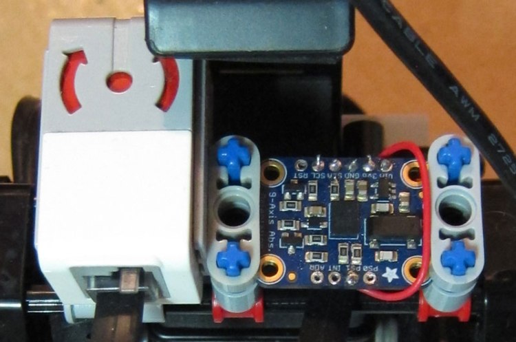
The picture above shows the device alongside the LEGO Gyro sensor, as you can see it is pretty small. This picture also shows the additional wire (between the PS1 pin and the 3V output) needed to tell the device to use the UART interface (by default it uses i2c). With this wire in place all that is required is to hook up the gnd(pin 3 red), 5V(pin 4 green) and UART tx(pin 6 blue) and rx(pin 5 yellow) connections to a standard EV3 cable and you are ready to start talking to the device.
A search for “BNO055 java” turns up the following useful page BNO055 9DOF Java Class for FRC roboRio I used the code from the associated github project as the basis for a first pass at a driver. I had to modify the code to use the leJOS UART interface and I also added methods to allow loading and saving of calibration data. The updated driver can be found here. Note that this code does not follow the leJOS sensor framework conventions and is a little rough around the edges, I will clean this up and the driver will probably appear in a later (post 0.9.1) version of leJOS. So with this code we can now access the device.
 static void initIMU(BNO055 imu)
 {
     if(!imu.begin(BNO055.opmode_t.OPERATION_MODE_NDOF)) {
         /* There was a problem detecting the BNO055 ... check your connections */
         System.out.println("Ooops, no BNO055 detected ... Check your wiring!");
         System.exit(0);
     }

     Delay.msDelay(1000);

     /* Display the current temperature */
     System.out.println("Current Temperature: " + imu.getTemp() + " C");

     imu.setExtCrystalUse(true);
     Delay.msDelay(2000);
     double[] pos = new double[3]; // [x,y,z] position data

     while(true)
     {
         pos = imu.getVector(BNO055.vector_type_t.VECTOR_EULER);
         System.out.print("X: " + pos[0] + " Y: " + pos[1] + " Z: " + pos[2]);
         cal = imu.getCalibration();
         System.out.println(" CALIBRATION: Sys=" + cal.sys + " Gyro=" + cal.gyro + " Accel=" + cal.accel + " Mag=" + cal.mag);
         Delay.msDelay(1000);
     }

 }
The above code initializes the IMU and sets it into full fusion mode. It then loops printing out the 3 Euler angles and the state of the calibration for the three sensors.
If you would like to see how this sensor can be used take a look at the following article Improving position tracking of a mobile robot which shows how the BNO055 can be used to improve the odometry used to track the position of a robot and also compares the device to the LEGO gyro.

Hi there,
Just wondering, you are using UART instead of I2C.
My question do you manage/try change the default setting by the manufacturer (eg: Gyro rate from 2000dps to 250dps) using UART?
Posted by Mohd Nabhan Fahmi | 2016/06/03, 18:17Yes I used the UART interface. I did have the i2c interface working but that required a hardware change to the board. I have not tried changing the gyro rate settings but other configuration commands work fine, assuming there are commands available in the command set to make such changes (check the data sheet for details) then I don’t see any reason why they would not work.
Posted by gloomyandy | 2016/06/03, 18:24What hardware changes did you do in the board? I have the board connected just as requested Vin, GND, SDA, SCL, and it is working. However, 2 things I dont like. First, I have lost the sensor while my drone is IN THE AIR ( Crahsed ofcourse), but no big deal I was flying low. I think I have fixed this by directly soldering all the pins to my respective Arduino pins (I was using headers, probably a weak connection). Second thing that I dont like is the “stretching”… I require a lot of time just to read some 6 bytes of Euler data. Could you advice? Would UART solve this?
Thanks in advance.
Posted by Oscar | 2016/07/19, 11:34The change I made to the board was to remove one of the built in i2c pull up resistors. But this change was LEGO specific and almost certainly not needed by you. The other hardware change was simply to add a link to enable the UART interface (rather then i2c). Sorry no idea if using the UART would be any better than i2c in terms of response time.
Posted by gloomyandy | 2016/07/19, 11:39Hi, I have a few questions: What does breakout mean, and what’s the difference between the original and the BNO055 IMU with the breakout board. Do I need more parts or cables to connect it to the EV3? What is ICU and UART? And can you please tell me the steps to make it ev3 compatible?
(Sorry for bad english)
Posted by Rares | 2017/06/20, 12:19A breakout board is a board that contains the basic chip plus additional components to make it easy to use. So for instance in this case you can use the BNO055 without having to attempt to solder surface mount components. I’m sure you can do a web search on UART to find out what it means. Assuming you mean MCU and not ICU then an MCU is a microcontroller (basically a small self contained computer). I’m sorry but if the above article is not sufficient to allow you to get things working then perhaps this is not the device for you. I’m not in a position to provide a step by step guide.
Posted by gloomyandy | 2017/06/20, 14:53