In a number of previous articles I’ve discussed a line following robot and the monitor program that runs on a PC to show the robot in action. This monitor program displays the position of the robot as it moves around the track. This position or Pose data is transmitted from the robot to the PC on a regular basis to allow the tracking program to update the position. It consists of the robot x, y position and orientation. This information is generated by a PoseProvider which is provided by the WheeledChassis class that supplies the motion control used by the line follower. This class makes use of Odometry which uses the data from the robots tachometers along with information about the wheel and chassis layout to track the robots movements. The mathematics is reasonably simple and the final form of the equations is:
In summary, our odometry equations for (x' , y' , θ' ) reduce to:
 dcenter = (dleft + dright)/2
 φ = (dright - dleft)/dbaseline
 θ' = θ + φ
 x' = x + dcenter*cos(θ)
 y' = y + dcenter*sin(θ)
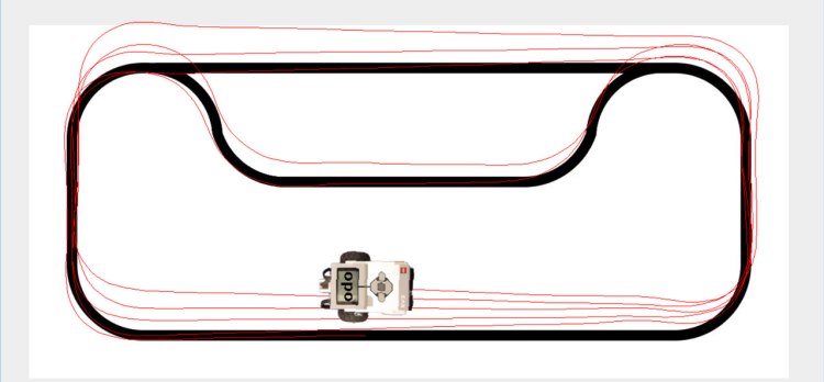
for more details see the A Primer on Odometry and Motor Control. This method of tracking works very well but over time due to wheel slippage and other issues the location information tends to drift. This is a well known problem with robots and has been studied in some detail. The major source of errors is typically tracking the robot turns, even very small errors here quickly build up into a large positional inaccuracy. A line following robot is an excellent test of how well position is tracked as it is constantly making small turns to track the line and these types of turn are tricky to follow accurately. The following image shows how the errors accumulate over a number of laps of the line following track:
One well established method of improving the accuracy for tracking turns is to use an additional sensor like a gyro or IMU to track the robot orientation while still using the tachometers to track the linear movement. A good explanation of this technique can be found in the following document IMU Odometry by David Anderson (well worth looking for other articles by David BTW). I’ve applied exactly this technique to the line follower using the BNO055 IMU, the results of this can be seen below (the green track is the IMU):
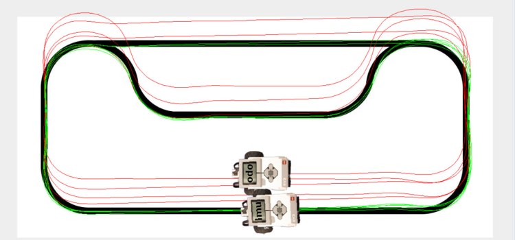
As you can see the IMU derived position tracks the line very closely. In these images the output is from the same series of laps with the robot sending multiple poses to the PC in this case one using standard odometry (red) with the other using the IMU to track the orientation (green).
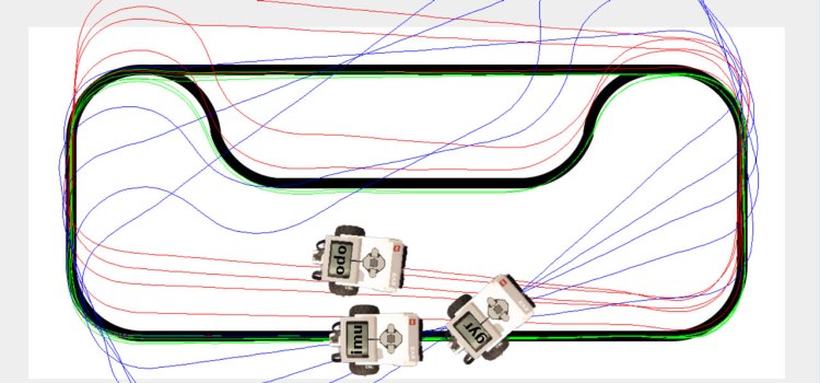
However not all gyros work so well. The final image:

shows the results of adding a pose that uses the LEGO gyro to track orientation(blue) and running the test again. As you can see in this case the gyro tracking is much worse than that obtained with standard odometry. I suspect that the major reason for this is the lack of resolution from the LEGO sensor. It provides output at 1 degree resolution, the BNO055 supports 16 times this. I used the LEGO device in angle mode which provides a direction orientation readout (the device integrates the angular velocity readings from the gyro sensor). It may be possible to improve on the results I obtained by using the velocity readings and performing the integration on the EV3 but earlier investigations of the gyro by Aswin would seem to indicate that this is unlikely. Another possible source of error is also described in this article, it seems that the LEGO sensor uses some form of filter (probably to avoid drift) that means that it ignores slow turns of the robot. This may mean that in effect the sensor is missing some of the small turns made when line following.
There is a video that shows the above tests in operation you can see it below:

One thing which may improve odometry might be the use of smaller wheels.
Posted by hfst | 2016/02/26, 21:58It may (because of the increase in counts per revolution), however depending upon the surface the robot is running on it a small wheel may not be able to cope with bumps and other issues as well as a larger one. A wider track (bigger distance between the wheels) may also help as turns will require more wheel movement (and so a larger tacho count).
Posted by gloomyandy | 2016/02/26, 23:25Can you tell me what ‘d’ in dcenter, dright, and dleft is?
I’m working on my final project, it’s Visual Inertial Odometry. I’m using BNO055 as well, but i still don’t understand how to get displacement data using quaternion, double integral etc. (based on references i got)
Posted by Chairul Huda | 2020/07/07, 05:07To understand the various terms used in the equations I included please see the original paper I referenced: https://ocw.mit.edu/courses/electrical-engineering-and-computer-science/6-186-mobile-autonomous-systems-laboratory-january-iap-2005/study-materials/odomtutorial.pdf
Posted by gloomyandy | 2020/07/07, 07:14